BALL VAVES
we're the best industrial uniontech
SBV10 SERIS BALL VALVES
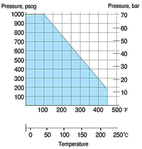
For working pressure up to 1000psig(69bar)
Features
- Compact design with hexagon bar-stock for high integrity
- Working pressure up to 1000psig(69bar) at 100°F(38°C)
- Low torque qurter turn actuation
- Size range of from 1/4 to 1 tubing and piping
- Various end connections : relible S-Lok, NTP & ISO male & female
- Butterfly handle is available as an option
Pressure - Temperature Ratings
Applications
Water, Oil, Gas
Petrocemical Plants
Steel mils
Heavy Vehicles
Factory Test
Every valve is factory tested with Nitrogen@1000psig(68bar) for leakage at the seat to a maximm allowable leak of 0.1 scc/min
The stem packing is tested for no detectable leakage.
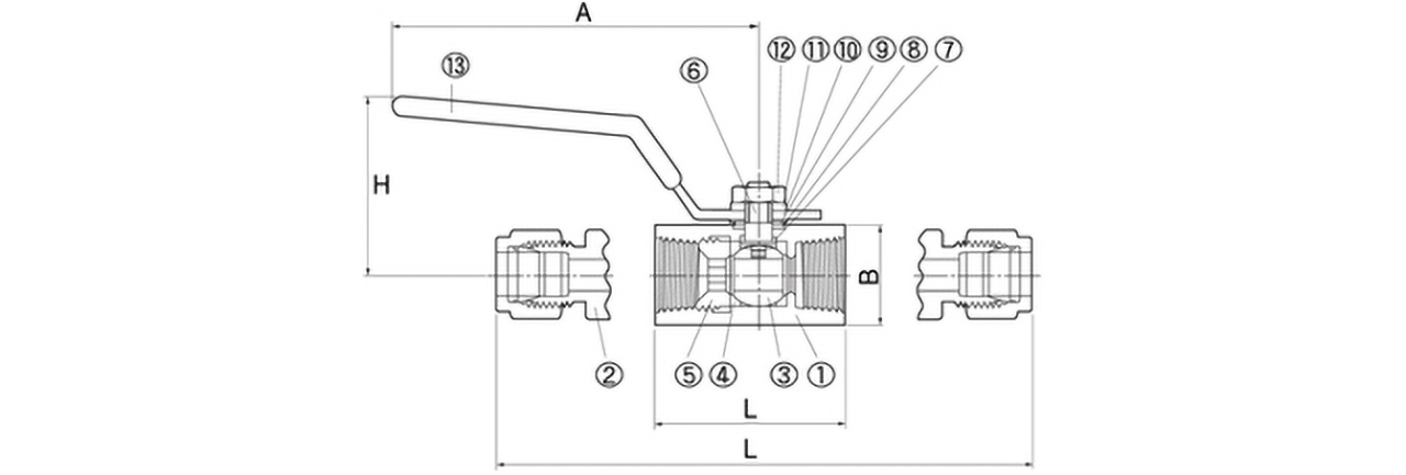
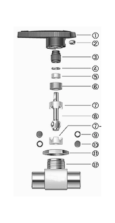
| NUMBER | ITEM | MATERIAL/ASTM SPECIFICATION | |
|---|---|---|---|
| 1 | Body | S316/A479/A276 | Brass/B16 |
| 2 | End Connector | S316/A479/A276 | Brass/B16 |
| 3 | Ball | S316/A479 | |
| 4 | Seat | Reinforced PTFE | |
| 5 | Insert | S316/A479 | |
| 6 | Steam | S316/A479 | |
| 7 | Lower Packing | Reinforced PTFE | |
| 8 | Upper Packing | Reinforced PTFE | |
| 9 | Grand | S304 | |
| 10 | Grand Washer | S304 | |
| 11 | Spring Washer | S304 | |
| 12 | Lock Nut | S304 | |
| 13 | Handle | S430 | |
Ordering Information and Dim ensions
| BASIC ORDERING NUMBER |
ORIFICE mm(in) |
CV | END CONNECTIONS Inlet/Outlet |
DIMENSION(mm) | ||||
|---|---|---|---|---|---|---|---|---|
| L | H | A | B | |||||
| SBV_ | S-6M | 5.0 | 1.25 | S-6M | 79 | 31 | 55 | 17 |
| S_4T | 1.25 | S_4T | 79 | |||||
| F_4N | 1.35 | F_4N | 40 | |||||
| SBV_ | S-10M | 7.5 | 2.60 | S-10M | 90 | 40 | 78 | 22 |
| S-6T | 2.50 | S-6T | 90 | |||||
| F_6N | 2.60 | F_6N | 45 | |||||
| SBV_ | S-12M | 9.0 | 9.25 | S-12M | 98 | 42 | 78 | 27 |
| S_8T | 9.25 | S_8T | 98 | |||||
| F_8N | 9.25 | F_8N | 54 | |||||
| SBV_ | S-10M | 7.5 | 2.60 | S-10M | 90 | 40 | 78 | 22 |
| S-6T | 2.50 | S-6T | 90 | |||||
| F_6N | 2.60 | F_6N | 45 | |||||
| SBV_ | S-16M | 12.5 | 10.60 | S-16M | 108 | 51 | 96 | 32 |
| S_10T | 10.60 | S_10T | 108 | |||||
| F_12N | 12.65 | F_12N | 63 | |||||
| S-12T | 12.65 | S-12T | 107 | |||||
| SBV_ | S-16T | 16.0 | 17.35 | S-16T | 133 | 55 | 96 | 38 |
| F-16N | 17.35 | F-16N | 74 | |||||
ORDERING INFORMATION
SAFETY IN VALVE SELECTION
The Selection of a valve for application or system design must be considered to ensure safe performance. Valve function, valve function, valve rating, material compatility, proper installation, operation and maintenance remain the sole reponsibility of the system designer and the user. UNION TECH accepts no liabilty for any improper selection, installation, operation or maintence.
SBV30 SERIS BALL VALVES
For working pressure up to 3000psig(206bar)
ORDERING INFORMATION
| HANBLE WITH ARROW |
Indicates flow direction Allows quick operation to open and close |
|---|---|
| PANEL MOUNTING NUT | Allow easy installation |
| VARIETY OF END CONNECTIONS |
Indicates flow direction Allows quick operation to open and close |
| ONE-PIECE BODY | Reduces the bumber of potential leak points. |
| ORIFFICE | Is optimized design for minimum pressure drop. |
| PACKING BOLT | Allow easy packing adjustment with valve in-line |
| PTFE PACKING | Is supported by top and bottom glands |
| ENCAPSULATING BALL SEATS |
Retains the capsule packing and prevent cold flow. |
| INTERGRAL BALL-STEM |
Is machined from one pieve bar stock Is best suited to encapsulte ball seats. |
Features
- Pressure rating up to 3000psig(206bar) @70°F(21°C)/li>
- Temperature rating from 50°F (10°C) to 150°F(65°C) with standard PTFE seat and packing
- Choice of materials : Standard S316 and available inalloy400 and Brass
- Vent to atmosphere available
- Every valve is 100% factory tested with the Nitrogen @1000psi(68bar)
Technical Data
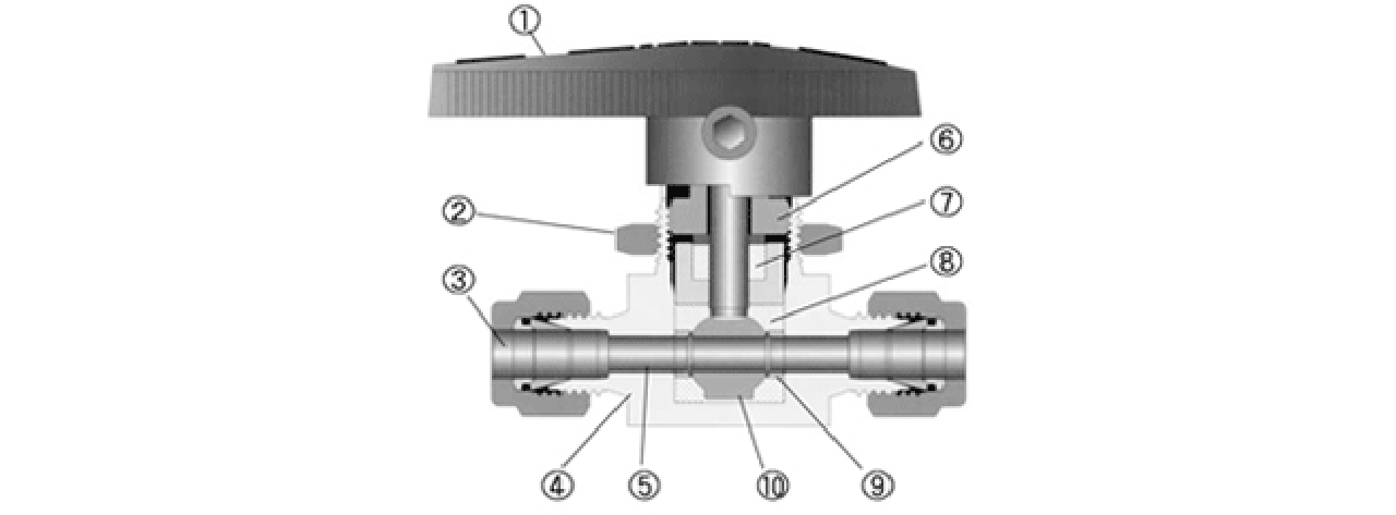
| Description | Grade / ASTM Specification | ||
|---|---|---|---|
| Valve Body Materials | |||
| S316 | Brass | ||
| 1 | Handle | Black Nylon | |
| 2 | Set screw | 17-4PH/A564 | |
| 3 | Packing bolt | S316/M79, A276 | Brass/616 |
| 4 | Upper grand | S316/A479, A276 | |
| 5 | Packing | PTFE/01710 | |
| 6 | Lower grand | S316/A479, Al76 | Brass/816 |
| 7&7-a | Upper&Lower Ball seat | PTFE/01710 | |
| 8 | Ball stem | S316/A479, A276 | |
| 9 | Support rings |
S316 (Fluorocarbon-coatod) |
|
| 10 | Side discs | ||
| 11 | Panel Nut | S316/A479, A276 | Brass/B16 |
| 12 | Body | ||
| Pressure Rating with standard PTFE seat | ||||
|---|---|---|---|---|
| Valve Designator | Straight 2-way | Angle 2-way | Switching 3-way | Temperature Range |
| SBV 1 | - |
50°F TO 150°F (10°C TO 65°C) |
||
| SBV 2 | 3000PSIG (206BAR) | 2500PSIG (172BAR) | ||
| SBV 3 | 2500PSIG(172BAR) | 1500PSIG(103BAR) | ||
| SBV 4 | ||||
2-Way (Shut-Off Valve)

Ordering Information and Dimensions
|
Basic Ordering Number |
Orifice | Cv | End Connections | ||||
|---|---|---|---|---|---|---|---|
| inline | angle | inline | angle | inlet | outlet | ||
| SBV1 | S-1T- | 1.3 | 0.052 | 0.01 | - | 1/16 S-Lok | |
| S-2T- | 2.4 | 0.093 | 0.2 | 0.15 | 1/8 S-Lok | ||
| S-3M- | 0.2 | 0.15 | 3mm S-Lok | ||||
| S-4T- | 3.2 | 0.125 | 0.6 | 0.35 | 1/4 S-Lok | ||
| S-6M- | 0.6 | 0.35 | 6mm S-Lok | ||||
| F-2N- | 0.5 | 0.3 | 1/8 Female NPT | ||||
| SBV2 | S-4T- | 4.8 | 0.187 | 2.4 | 0.9 | 1/4 S-Lok | |
| S-6T- | 1.5 | 0.9 | 3/8 S-Lok | ||||
| S-6M- | 2.4 | 0.9 | 6mm S-Lok | ||||
| S-8M- | 1.5 | 0.9 | 8mm S-Lok | ||||
| F-2N- | 1.2 | 0.7 | 1/8 Female NPT | ||||
| F-4N- | 0.9 | 0.75 | 1/4 Female NPT | ||||
| M-4N- | 1.2 | 0.75 | 1/4 Female NPT | ||||
| M-4R- | 0.9 | 0.75 | 1/4 ISO Female Tapered | ||||
| SBV3 | S-6T- | 7.1 | 0.281 | 6.0 | 2.0 | 3/8 S-Lok | |
| S-10M- | 6.0 | 2.0 | 3/8 S-Lok | ||||
| F-4N- | 3.0 | 1.7 | 1/4 Female NPT | ||||
| F-6N- | 2.6 | 1.5 | 3/8 Female NPT | ||||
| S-6R- | 2.6 | 1.5 | 3/8 ISO Female Tapered | ||||
| SBV4 | S-8T- | 10.3 | 0.406 | 12.0 | 4.6 | 1/2 S-Lok | |
| S-12T- | 6.4 | 3.8 | 3/4 S-Lok | ||||
| S-12M- | 9.5 | 0.375 | 12.0 | 4.6 | 12mm S-Lok | ||
| S-8N- | 10.3 | 0.406 | 6.0 | 3.5 | 1/2 Female NPT | ||
| S-8R- | 6.3 | 3.5 | 1/2 ISO Female Tapered | ||||
|
Basic Ordering Number |
Dimensions (mm) | ||||||||||||
|---|---|---|---|---|---|---|---|---|---|---|---|---|---|
| A | L1 | L2 | H3 | H2 | H1 | F | T1 | T2 | G | H | W | ||
| SBV1 | S-1T- | 42.7 | 21.3 | - | 8.6 | 7.1 | 28.4 | 6.4 | 2.0 | 15.1 | 34.5 | 14.7 | |
| S-2T- | 51.1 | 25.6 | 24.6 | ||||||||||
| S-3M- | 51.1 | 25.6 | 24.6 | ||||||||||
| S-4T- | 56.1 | 28.1 | 27.2 | ||||||||||
| S-6M- | 56.1 | 28.1 | 27.2 | ||||||||||
| F-2N- | 41.1 | 20.6 | 20.6 | ||||||||||
| SBV2 | S-4T- | 59.9 | 30.0 | 29.7 | 11.2 | 9.7 | 38.9 | 4.8 | 2.5 | 19.8 | 39.6 | 19.8 | |
| S-6T- | 65.5 | 32.8 | 32.8 | ||||||||||
| S-6M- | 60.7 | 25.6 | 24.6 | ||||||||||
| S-4T- | 56.1 | 28.1 | 27.2 | ||||||||||
| S-6M- | 56.1 | 28.1 | 27.2 | ||||||||||
| F-2N- | 50.8 | 25.4 | 25.4 | ||||||||||
| F-4N- | 52.3 | 26.2 | 26.2 | ||||||||||
| M-4N- | 50.8 | 25.4 | 26.2 | ||||||||||
| F-4R- | 52.3 | 26.2 | - | ||||||||||
| SBV3 | S-6T- | 77.5 | 38.8 | 36.3 | 14.2 | 14.2 | 50.8 | 9.5 | 3.0 | 28.6 | 52.6 | 28.4 | |
| S-10M- | 78.0 | 38.9 | 36.9 | ||||||||||
| S-4N- | 63.5 | 31.8 | 31.8 | ||||||||||
| S-6N- | 63.5 | 31.8 | 31.8 | ||||||||||
| S-6R- | 63.5 | 31.8 | - | ||||||||||
| SBV4 | S-8T- | 99.6 | 49.8 | 44.2 | 17.5 | 17.5 | 76.2 | 9.5 | 3.0 | 38.1 | 61.7 | 38.1 | |
| S-12T- | 99.6 | 49.8 | 44.2 | ||||||||||
| S-12M- | 99.6 | 49.8 | 44.2 | ||||||||||
| S-8N- | 79.2 | 39.6 | 39.6 | ||||||||||
| S-8R- | 79.2 | 39.6 | - | ||||||||||
All dimension shown are for reference only and are subject to change to change. Dimensions with S-Lok nuts are in finger-tight position.
Patterns: To order angle pattern, use-A as a suffix to the basic ordering number. Example:SBV1-D-4-A-S
| FLOW RATE | ||||||||||||||||
|---|---|---|---|---|---|---|---|---|---|---|---|---|---|---|---|---|
|
Pressure Drop To Atomosphere(△P) in psi |
Cv | |||||||||||||||
| 0.1 | 0.2 | 0.5 | 0.6 | 0.9 | 1.2 | 1.5 | 1.6 | 2.4 | 2.6 | 3.0 | 6.0 | 6.3 | 6.4 | 12.0 | ||
|
AIR SCFM @70°F(21°C) |
10 | 1.1 | 2.7 | 6.9 | 8.3 | 12.0 | 17.0 | 21.0 | 22.0 | 33.0 | 36.0 | 41.5 | 83.0 | 87.2 | 88.6 | 166.0 |
| 50 | 3.0 | 7.6 | 19.1 | 23.0 | 34.0 | 46.0 | 57.0 | 61.0 | 92.0 | 99.5 | 115.0 | 230.0 | 241.0 | 245.0 | 459.0 | |
| 100 | 5.3 | 14.0 | 33.9 | 40.7 | 61.0 | 81.0 | 100.0 | 110.0 | 160.0 | 176.0 | 203.0 | 407.0 | 427.0 | 434.0 | 814.0 | |
|
WATER US GPM @70°F(21°C) |
10 | 0.3 | 0.6 | 1.6 | 1.9 | 2.8 | 3.7 | 4.7 | 5.0 | 7.5 | 8.2 | 9.5 | 19.0 | 19.9 | 20.2 | 37.9 |
| 50 | 0.7 | 1.4 | 3.5 | 4.2 | 6.3 | 8.4 | 11.0 | 11.0 | 17.0 | 18.4 | 21.2 | 42.3 | 44.5 | 45.5 | 84.9 | |
| 100 | 1.0 | 2.0 | 5.0 | 6.0 | 9.0 | 12.0 | 15.0 | 16.0 | 24.0 | 26.0 | 30.0 | 60.0 | 63.0 | 64.0 | 120.0 | |
The Cv is for the straight pattern valves, Cvs of angle pattern vavlves are the same as those of 3-way valves.
3-Way switching Valves
Ordering Information and Dimensions
|
Basic Ordering Number |
Orifice | Cv | End Connections | ||
|---|---|---|---|---|---|
| mm | inch | ||||
| SBV1-3B | S-1T- | 1.3 | 0.052 | 0.08 | 1/16 S-Lok |
| S-2T- | 2.4 | 0.093 | 0.15 | 1/8 S-Lok | |
| S-4T- | 3.2 | 0.125 | 0.35 | 1/4 S-Lok | |
| S-3M- | 2.4 | 0.093 | 0.15 | 3mm S-Lok | |
| S-6M- | 3.2 | 0.125 | 0.35 | 6mm S-Lok | |
| F-2N- | 3.2 | 0.125 | 0.3 | 1/8 Female NPT | |
| SBV2-3B | S-4T- | 4.8 | 0.187 | 0.90 | 1/4 S-Lok |
| S-6M- | 0.9 | 6mm S-Lok | |||
| S-8M- | 0.9 | 8mm S-Lok | |||
| F-4N- | 0.75 | 1/4 Female NPT | |||
| F-4R- | 0.75 | 1/4 ISO Female Tapered | |||
| SBV3-3B | S-6T- | 7.1 | 0.281 | 2.0 | 3/8 S-Lok |
| S-10M- | 2.0 | 10mm S-Lok | |||
| S-4N- | 1.7 | 1/4 Female NPT | |||
| S-6N- | 1.5 | 3/8 Female NPT | |||
| S-6R- | 1.5 | 3/8 Female Tepered | |||
| SBV4-3B | S-8T- | 10.3 | 0.406 | 4.6 | 1/2 S-Lok |
| S-12T- | 10.3 | 0.406 | 3.8 | 3/4 S-Lok | |
| S-12T- | 10.3 | 0.406 | 3.8 | 3/4 S-Lok | |
| S-12M- | 9.5 | 0.375 | 4.6 | 12mm S-Lok | |
| F-8N- | 10.3 | 0.406 | 3.5 | 1/2 Female NPT | |
| F-8R- | 10.3 | 0.406 | 3.5 | 1/2 ISO Female Tapered | |
|
Basic Ordering Number |
Dimensions (mm) | |||||||||||
|---|---|---|---|---|---|---|---|---|---|---|---|---|
| A | L1 | H1 | H2 | F | T1 | T2 | G | H | W | |||
| SBV1-3B | S-1T- | 42.7 | 21.3 | 20.6 | 8.6 | 28.7 | 6.4 | 2.0 | 15.1 | 34.5 | 14.7 | |
| S-2T- | 51.1 | 25.6 | 24.6 | |||||||||
| S-4T- | 56.1 | 28.1 | 27.2 | |||||||||
| S-3M- | 51.1 | 25.6 | 24.6 | |||||||||
| S-6M- | 56.1 | 28.1 | 27.2 | |||||||||
| F-2N- | 41.1 | 20.6 | 20.6 | |||||||||
| SBV2-3B | S-4T- | 60.7 | 30.4 | 29.7 | 11.2 | 38.9 | 4.8 | 2.5 | 19.8 | 39.6 | 19.8 | |
| S-6M- | 60.7 | 30.4 | 29.7 | |||||||||
| S-8M- | 62.5 | 31.2 | 30.5 | |||||||||
| F-4N- | 52.3 | 26.2 | 26.2 | |||||||||
| F-4R- | 52.3 | 28.1 | 27.2 | |||||||||
| SBV3-3B | S-6T- | 73.4 | 36.7 | 36.3 | 14.2 | 50.8 | 9.5 | 3.0 | 28.6 | 52.6 | 28.4 | |
| S-10M- | 73.4 | 36.7 | 36.3 | |||||||||
| S-4N- | 63.5 | 31.8 | 31.8 | |||||||||
| F-6N- | 63.5 | 31.8 | 31.8 | |||||||||
| F-6R- | 63.5 | 31.8 | 31.8 | |||||||||
| SBV4-3B | S-8T- | 88.4 | 44.2 | 44.2 | 17.2 | 76.2 | 9.5 | 3.0 | 38.1 | 61.7 | 38.1 | |
| S-12T- | 88.4 | 44.2 | 44.2 | |||||||||
| S-12M- | 88.4 | 44.2 | 44.2 | |||||||||
| F-8N- | 79.5 | 39.8 | 39.6 | |||||||||
| F-8R- | 79.5 | 39.8 | 39.6 | |||||||||
All dimension shown are for reference only and are subject to change. Dimensions with S-Lok nuts are in finger-tight position.
| FLOW RATE | ||||||||||||||||
|---|---|---|---|---|---|---|---|---|---|---|---|---|---|---|---|---|
|
Pressure Drop To Atomosphere(△P) in psi |
Cv | |||||||||||||||
| 0.08 | 0.15 | 0.30 | 0.35 | 0.75 | 0.8 | 0.9 | 1.5 | 1.7 | 2.0 | 3.5 | 3.8 | 4.6 | ||||
|
AIR SCFM @70°F(21°C) |
10 | 0.9 | 2.0 | 4.2 | 4.8 | 10.0 | 11.0 | 12.0 | 20.8 | 23.5 | 27.7 | 48.4 | 52.6 | 63.7 | ||
| 50 | 2.4 | 5.7 | 11.5 | 13.4 | 29.0 | 31.0 | 34.0 | 57.4 | 65.0 | 76.5 | 134.0 | 145.0 | 176.0 | |||
| 100 | 4.3 | 10.1 | 20.3 | 23.7 | 51.0 | 54.0 | 61.0 | 102.0 | 115.0 | 136.0 | 237.0 | 258.0 | 312.0 | |||
|
WATER US GPM @70°F(21°C) |
10 | 0.3 | 0.4 | 0.9 | 1.1 | 2.3 | 2.5 | 2.8 | 4.7 | 5.4 | 6.3 | 11.1 | 12.0 | 14.5 | ||
| 50 | 0.6 | 1.0 | 2.1 | 2.5 | 5.3 | 5.6 | 6.3 | 10.6 | 12.0 | 14.1 | 24.7 | 26.9 | 32.5 | |||
| 100 | 0.8 | 1.5 | 3.0 | 3.5 | 7.5 | 8.0 | 9.0 | 15.0 | 17.0 | 20.0 | 35.0 | 38.0 | 46.0 | |||
Packing Adjustment
- SBV30 valves are designed to control fluid in full open and closed position ; usion SBV30 valves to throttle the flow may reduce the valve life.
- Every valves are factory adjusted for 1000psig service at 70 21
- For use i higher pressure, the packing must be readjusted.
- Exposure of valves to varying temperature can affect the initial packing load You may need check leak and readjust packing bolt.
- Packing adjustment may be required during the valve in service
Vent Hole Option
Downstream vent hole is open used with instrument or gauges. When the valve is in the on position, pessure is applied to the Gauge or instrument.
When the valve is turned off, the instrument or gauge is vented to atmosphere through a hole in the side of the valve body and upstream port is closed to fluid flow. The maximum working pressure of the valve with the vented hole Option is limited to 500psig (34bar)/
Testing
- Every valve is factory tested for bubble-tight leakage at both seat and stem packing with nltrogen at 1000psi(69bar).
- Seats hav a maximum allowable leak rate of 0.1sccm/min. Optional tests are available upon request.
Choice of Stem Tip's available